Monday, 16 January 2017

Done!! Well, almost

It's Sunday, and very wet outside, so what else would you do, if not finish up the build?

First job is to assemble the second speaker, like the first. Trickier - the hole for the woofer tube was a much tighter fit, and took some serious clouting with the rubber hammer!

Then the wiring completion, basically 
  • Cut to length, leaving plenty inside the woofer tube to enable removal of the speaker units at some future date
  • Check the polarity and wiring with a 1.5v battery
  • Fit the crimped on tag connectors
  • Push them onto the Speakon terminals
  • Screw the Speakons into the bases

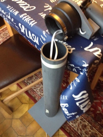
Speakon connector in place
I also cut the 2x5m Speakon connector cables - one 10m length with a plug on each end, now cut into two, and prepared the ends, bare wire being required for connection to the Sony output terminals. I also plugged the connectors into the speakers and re-checked the wiring and polarity with the 1.5v battery. Success!

All done, in the front room for a team picture
The initial setup and so on was quite fraught - I haven't used the Sony amp much, and various bits seemed not to work, but eventually I checked all the wiring, connections, input settings and so on and - bingo!! The Kraken wakes!
Speakers in initial operation
And here they are. They are in front of my Quad ESL63s and existing amps/sources. The Sony amp and miniDSP are on the floor between them.

What do they sound like? Good! At least, not utter shyte, which was always possible. Good bass, more punchy than the Quads. Top end seems ok. They don't sound like boxes as I perceive them (result). Jen and I listened to lots of music, and got very aurally tired! Do they replace the Quads, the original design brief? I'm not sure yet, but it's possible... It's conceivable that a better DSP/Amp setup could add a lot, but let's see how it goes. The subwoofer would also improve the bass and free up the current woofer to do a better lower midrange job.

Almost done? Yes, well, I haven't checked for air least yet with a 10Hz signal - I had to get them connected to the amp to check that, and then got carried away listening! Tomorrow??

I have also had a fiddle with the gain structure again. I suspect the miniDSP is about 16db hotter than the Sony inputs can handle, but it doesn't seem to be a problem. I've looked at the Sony circuit diagrams to work out where the input attenuation takes place, if it's in the right place then just turning it down is sufficient to prevent distortion, but it's not obvious to me. Otherwise, the miniDSP input meters show that most material appears to be getting near the 0dB level, which is pretty scary. I re-ran the tests with the HiFi News signals off a CD and the REW signal generator, and the miniDSP levels appear fairly close to accurate, which is pleasing. At least I can ensure that the miniDSP doesn't clip, as it's ADCing the input - that would be dull! I guess I could get a miniDSP miniDigi and strap it onto the miniDSP so that I skip a DAC/ADC step. Another time...


Thursday, 12 January 2017

Final Assembly - One Down, One To Go!

Right, here goes... This turns out to be quite tricky.

Firstly, I have to assemble the FR tube onto the mounting plate. I had a couple of goes at this, because getting the levelling screws a) level (!) b) at the right height was a bit tricky. This also involved running the cable through the tube and blocks, which required an additional reaming with the 5mm drill bit to straighten the holes up.

Initial FR tube mounting on plate
Running the FR wires through the block is tricky, and adds to the complexity of putting the nuts and washers on the retaining bolts. But...

Attachment bolts with FR wires, showing tightness of spot!
After that the wire needed to be run through the hole in the coupler - this was also a bit hard! The wire is not very bendy and needs eventually to turn at right angles a) at the exit from the mounting plate b) on the inside of the coupler, after it's come through the side.

View of FR wire transit from mounting plate to coupling 
Of course, I aligned the speaker terminals with the rear of the coupler, right where the FR wires come through... this increased the level of difficulty by about 5! But eventually I coaxed it into place, and worked the 1m of wire through the hole.

FR wires enter right beside Woofer speaker terminals!!
Now it was time to assemble the woofer tube to the base, and then the rubber coupler to the woofer tube. This is/was made difficult by the need to run the wires through the base, whilst not actually connecting the coupler to the woofer tube. Fortunately the dining room table is about the right height to support the heavy speaker assembly whilst the tube and base are unstressed and can be assembled.

Speaker units resting on table
I used the "dodgy" glue because it's pretty darned good on anything but EPDM, and can be more easily applied than the pretty gloopy acrylic stuff. I also checked the tube's orthogonality using a set square, and pounded it into the hole with a rubber mallet!

What I haven't included pictures of is the teasing out of the two 1' x 2' pieces of MDM4 wadding - that was a major component of the time, and was pretty tiring, just pulling at the wadding to open it up. Eventually I got it done, rolled up and stuffed down the woofer tube...

At which point I was able to put the coupler on the woofer tube and tighten the stainless steel band. Hurrah!
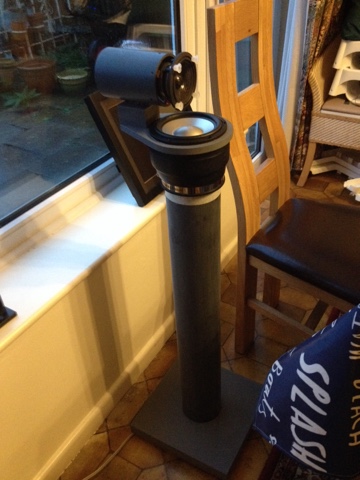
Completed speaker assembly
And here's the result. I still have to remove the draughting tape that marks the 1" level of the coupler on the tube, and fill the coupler and base wire holes with sealant. Then it's done!

I'm really impressed - it looks great, really solid, and the colours work brilliantly, giving a kind of solidity and technical "function over form" appearance. It's not an eyesore, and quite neutral.

Wednesday, 11 January 2017

Damn! The wrong kind of glue...

I was a bit suspicious about the glue I'd used for the woofer EPDM (synthetic rubber) couplers. The glue (Evostick "Sticks Like ...") just didn't seem to be setting where it was in contact with the EPDM, and some investigation today proved that it was useless. A quick Google on EPDM revels that only cyanoacrylate (superglue) really sticks to EPDM, because it's slightly oily, being made out of, well, oil. The next best stuff is acrylic glue - and at that point I recall that the Magic521 kit includes some acrylic glue...

A quick scan of the Magic521 instructions reveals they are supplying Soudal Fix All, or at least, that's what I worked out after some judicious Googling. And Screwfix has various types. Hurray.

An hour's worth of pulling apart and careful scraping cleans up the couplers and the mounting rings. At least, I hope it does. It's hard to know. And I do have to be careful because the speakers are of course still glued into the mounting plates, and are easily damaged with a scraper or screwdriver blade. I have managed not to damage them, unusually.

So tonight I've reglued the couplers and mounting plates, using Soudal Fix All High Tack, which is incredibly thick and hard to use. It is, however, clear, which is handy, and smells a lot more pleasant than the Sticks Like, being solvent-free. Let's see how these look tomorrow.

UPDATE: The new glue appears to stick really well! Success. Phew. 

Sunday, 8 January 2017

Getting close! Woofers, bases... Almost done

It being Sunday afternoon, and a few moments to myself, time for a little more assembly. 

I glued the woofers into the mounting plates, after clipping the wiring onto the back of the units - it would be really hard to do that afterwards. Prior to that I also drilled holes in the backs of the couplers to pass the FR unit wires through so that everything runs inside the woofer tubes. That was actually quite hard - the coupler material is extremely tough and resilient - I ended up using a sharp knife to cut some material out of the holes.

Woofers newly glued into the mounting plates
I also attached the feet onto the bases. I had been going to use 3 feet, on the basis that they wouldn't need levelling or truing, but since I wanted two get at the front and the back one would have gone where the Speakon socket is, I went with four. 

Attached base feet - it's underneath, right?

The feet look quite good, IMHO! 
I also resanded the woofer tubes and put a ring of tape 1" from the top, in readiness for mounting the speaker units on the top. I suspect this final stage is going to be the trickiest, since it involves
  • Mounting the FR tubes on the mounting plates - I have to adjust the height/levelling screws too; MagicLX521 suggests using a 5mm drill bit to get the height right, good idea
  • Finishing running the wiring from the FR and Woofer through the woofer tubes - involves running it through the FR tube mounting blocks and the couplings/woofer mounts, and then down through the holes in the bases; hopefully I've left enough wire spare for this! MagicLX521 glue the tube to the base first, then run the wires through the base; this is probably a good idea, since will allow me to push on the top of the tube to get it into the hole! I'd better check I can reach down the tube far enough to push the wires in the holes in the base...
  • Putting the filling in the woofer tubes - the MagicLX521 kit suggests just pushing it in from the top, rather than from the bottom like Linkwitz. Since that uses a similar mount for the tubes (a hole in the base, rather than the original cup), I shall likely do the same. 
  • Attaching the woofer tubes to the bases - a one-time job since it will use the acrylic glue, so better get this right...
  • Attaching the couplers/mounting plates to the woofer tubes - that doesn't sound too hard, does it :-p
  • Cutting the wires to length, attaching the crimp-on connectors, attaching to the Speakon connectors and screwing the connectors into the bases
  • Filling the FR tubes with damping; I won't have any MDM-4 left, since it all appears to go into the woofer tubes! I'm going to use BAF that I already have, let's hope it has the right effect, otherwise acquiring another pack of MDM-4 is going to be very expensive (relatively). the MagicLX521 kit also uses two packs of MDM-3 (originally), the same size as the MDM-4, and just says "use both both sheets; stuff the FR tube with lots of wadding" without pointing out exactly where the FR tube wadding is coming from. Ha! I guess I could email them for a pointer.


Saturday, 7 January 2017

Some progress - building the FR tubes!

It's been slow over the holiday period, all those dratted people requiring attention ;). I'm not sure that things would necessarily have gone any better, I'd have just screwed up sooner!

I spent this afternoon building the FR speaker enclosures. Firstly, the slightly misaligned bolt holes make it tricky to get the hardboard pads in the right place. Hopefully they're OK. I also thought I'd try double sided tape instead of hot glue to attach the pads to the units, as last time the glue seemed to come off very easily! However, it doesn't provide any filling effect so the pads are liable to move around a bit and also rock if not exactly centrally pressured, which they're not. Boo. We'll see. Additionally, it's very hard to tighten the nuts on the nonslip washers, no spanner I have fits and allows the turning of the nut in the available space.


I've also (gulp) glued the rubber couplers onto the mounting plates. They are currently drying under the mild pressure of a box of champagne - amazing what you find in the garage. I have yet to drill the holes for the FR wires to go through them, I'll do that when they're dry. I think it's a good idea to glue couplers and speakers separately, it enables me at least to get the former well-attached!!


Hopefully, the various cruddinesses will neither make the end result non-functional or too horrible in appearance. We'll see!!


Monday, 2 January 2017

Slow progress with Bozo AKA yet more mistakes!

Grimness. I am actually Bozo the clown... I checked the alignment of the FR chassis units in the FR tubes, having managed to stick the hardboard pads on with a hot glue gun. For some reason, I couldn't make the speaker be the right height in the tube - the pads were too high! Then I looked again at the plans - I'd drilled the stupid holes at 0.5" from the top, not 0.25"! Fool. And there isn't really space for a new 5mm hole beside the old 5mm hole without breaking through the side...

Fortunately, I'd gone for a 3 bolt solution, with two bolts at the bottom and one centrally at the top. So I was able to reverse that, so now it's one at the bottom and 2 at the top. And I remembered this time to use a 4mm drill, and use the 5mm taps I have to tap a proper 5mm thread into those holes! So it was kind of a result. Some pictures...
Set screws looking cool in the new tapped hole

Originally specified bolt in tapped hole - original hole also visible!
Set screw screwed in vs. cap screw
The set screws are pretty cool looking, if only I'd put the holes and the taps in the right place the first time! Sigh...

I ended up taking the pads off the speaker units of course, because they are now in the wrong place. Fortunately the glue didn't appear to have adhered too well, and they came off far too easily!

I've also been spraying the various parts over the holiday on the occasion that it's not too cold or wet outside, and there are no micro-people around who will DIE if they inhale overspray. They required an additional can of paint - the bases are really sucking the paint up, but typically MDF is never going to accept a finish on the cut edges without some kind of primer. Ha! I don't care. It's industrial chic, right?